아두이노 MPU6050 자이로 가속도센서 실습
MPU6050 자이로 가속도센서는 단일 칩에 MEMS(마이크로 전자 기계 시스템) 가속계와 MEMS 자이로를 포함하고 있습니다. 이 센서는 3축 자이로스코프와 3축 가속도계를 모두 포함하고 있으며 독립적으로 측정이 가능합니다. I2C 포트를 통해 아두이노 보드와 통신합니다.
MPU6050 센서는 드론, RC비행기, 짐벌 등과 같이 주로 3차원 위치제어를 통해 균형을 잡을 필요가 있는 곳에 사용됩니다. 이를 제어하기 위한 3가지 요소가 요(Yaw), 롤(Roll), 피치(Pitch)입니다.
아래 그림은 비행기의 무게중심에서 직각으로 교차하는 세 개의 선을 그리고 여기에 요(Yaw), 롤(Roll), 피치(Pitch)의 개념을 표시하였습니다.
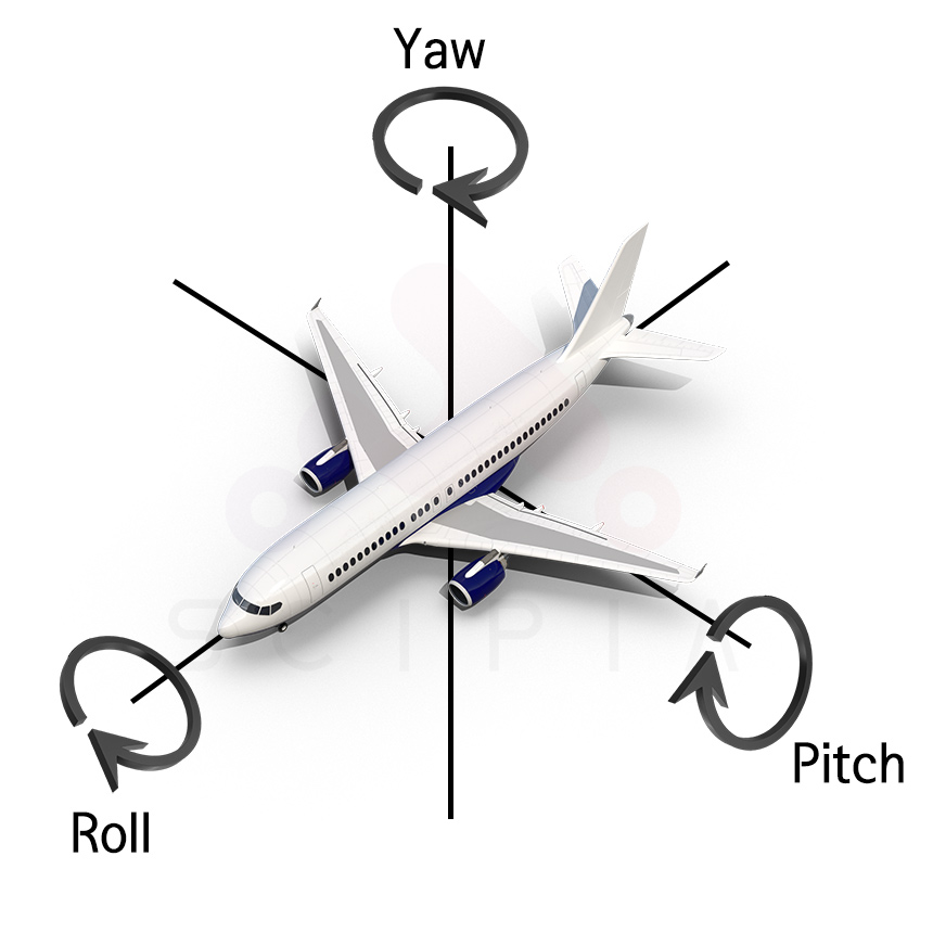
- 롤(Roll)은 앞뒤 축을 중심으로 회전하는 것을 말합니다.
- 피치(Pitch)는 측면 축 주변으로 회전하는 것을 말합니다. 주로 고도 변경을 위해 사용됩니다.
- 요(Yaw)는 수직축을 중심으로 회전하는 것을 말합니다.
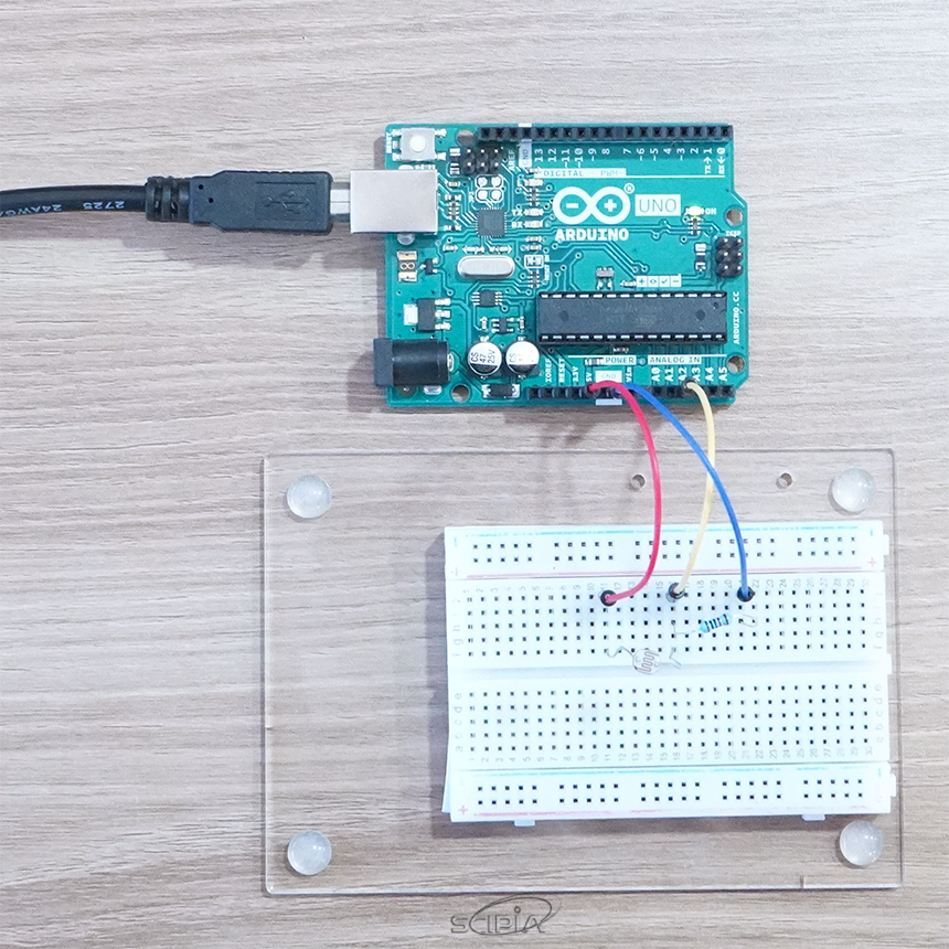
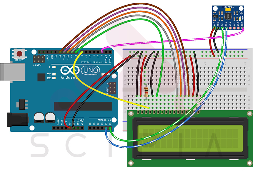
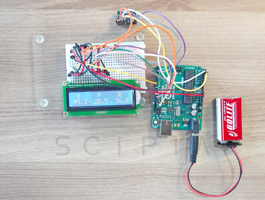
아래는 아두이노 보드와 MPU6050을 사용하여 LCD에 요(Yaw), 롤(Roll), 피치(Pitch) 값을 표시하는 회로입니다.

라이브러리는 아래 링크에서 다운로드하고 아두이노 프로그램 메뉴에서 스케치->라이브러리 포함하기->.ZIP 라이브러리 추가를 누르고, 파일선택창이 나오면 다운받은 라이브러리 파일을 선택하시면 됩니다.
라이브러리
소스코드
아래는 소스코드입니다. 아두이노 IDE에 붙여넣기 하여 컴파일하고 업로드합니다.
#include <LiquidCrystal.h>
#include "I2Cdev.h"
#include "MPU6050_6Axis_MotionApps20.h"

#if I2CDEV_IMPLEMENTATION == I2CDEV_ARDUINO_WIRE
    #include "Wire.h"
#endif

LiquidCrystal lcd(7,8,9,10,11,12);//RS,E,DB4,DB5,DB6,DB7

MPU6050 mpu;

#define INTERRUPT_PIN 2  // 인터럽트 핀
#define LED_PIN 13 // 아두이노 내장 LED
bool blinkState = false;

// MPU6050 제어 및 상태표시 변수
bool dmpReady = false;  // set true if DMP init was successful
uint8_t mpuIntStatus;   // holds actual interrupt status byte from MPU
uint8_t devStatus;      // return status after each device operation (0 = success, !0 = error)
uint16_t packetSize;    // expected DMP packet size (default is 42 bytes)
uint16_t fifoCount;     // count of all bytes currently in FIFO
uint8_t fifoBuffer[64]; // FIFO storage buffer

// 요롤피치 계산용
Quaternion q;           // [w, x, y, z]         4원법 변수
VectorFloat gravity;    // [x, y, z]            중력 벡터
float ypr[3];           // [yaw, pitch, roll]   요롤피치 변수

int intCount;

volatile bool mpuInterrupt = false;     // MPU6050 인터럽트 발생유무 확인용
// 인터럽트 루틴
void dmpDataReady() {
    mpuInterrupt = true;
}


void setup() {

    #if I2CDEV_IMPLEMENTATION == I2CDEV_ARDUINO_WIRE
        Wire.begin();
        Wire.setClock(400000); // 400kHz I2C clock. Comment this line if having compilation difficulties
    #elif I2CDEV_IMPLEMENTATION == I2CDEV_BUILTIN_FASTWIRE
        Fastwire::setup(400, true);
    #endif

    lcd.begin(16,2);
    intCount = 0;

    Serial.begin(9600);
    while (!Serial);

    //초기화
    Serial.println(F("Initializing I2C devices..."));
    mpu.initialize();
    pinMode(INTERRUPT_PIN, INPUT);

    //MPU6050과 연결상태 확인
    Serial.println(F("Testing device connections..."));
    Serial.println(mpu.testConnection() ? F("MPU6050 connection successful") : F("MPU6050 connection failed"));

    //요롤피치 산출을 위한 DMP(Digital Motion Processor) 초기화
    Serial.println(F("Initializing DMP..."));
    devStatus = mpu.dmpInitialize();

    //옵셋 설정
    mpu.setXGyroOffset(220);
    mpu.setYGyroOffset(76);
    mpu.setZGyroOffset(-85);
    mpu.setZAccelOffset(1688);

    //정상동작여부 확인 0이면 정상
    if (devStatus == 0) {
        //DMP 활성화
        Serial.println(F("Enabling DMP..."));
        mpu.setDMPEnabled(true);

        //아두이노 인터럽트 활성화
        Serial.print(F("Enabling interrupt detection (Arduino external interrupt "));
        Serial.print(digitalPinToInterrupt(INTERRUPT_PIN));
        Serial.println(F(")..."));
        attachInterrupt(digitalPinToInterrupt(INTERRUPT_PIN), dmpDataReady, RISING);
        mpuIntStatus = mpu.getIntStatus();

        //DMP 대기상태
        Serial.println(F("DMP ready! Waiting for first interrupt..."));
        dmpReady = true;

        // DMP패킷 크기 비교
        packetSize = mpu.dmpGetFIFOPacketSize();
    } else {
        // ERROR!
        // 1 = initial memory load failed
        // 2 = DMP configuration updates failed
        // (if it's going to break, usually the code will be 1)
        Serial.print(F("DMP Initialization failed (code "));
        Serial.print(devStatus);
        Serial.println(F(")"));
    }

    //LED 포트 출력으로 설정
    pinMode(LED_PIN, OUTPUT);
}

void loop() {
    // 오류시 종료
    if (!dmpReady) return;

    //MPU6050 데이터 대기
    while (!mpuInterrupt && fifoCount < packetSize) {
        if (mpuInterrupt && fifoCount < packetSize) {
          // try to get out of the infinite loop
          fifoCount = mpu.getFIFOCount();
        }
        // 사용자 프로그램은 여기에 작성
        // .

    }

    // 인터럽트 플래그를 리셋
    mpuInterrupt = false;
    mpuIntStatus = mpu.getIntStatus();

    // get current FIFO count
    fifoCount = mpu.getFIFOCount();

    // check for overflow (this should never happen unless our code is too inefficient)
    if ((mpuIntStatus & _BV(MPU6050_INTERRUPT_FIFO_OFLOW_BIT)) || fifoCount >= 1024) {
        // reset so we can continue cleanly
        mpu.resetFIFO();
        fifoCount = mpu.getFIFOCount();
        Serial.println(F("FIFO overflow!"));

    // otherwise, check for DMP data ready interrupt (this should happen frequently)
    } else if (mpuIntStatus & _BV(MPU6050_INTERRUPT_DMP_INT_BIT)) {
        // wait for correct available data length, should be a VERY short wait
        while (fifoCount < packetSize) fifoCount = mpu.getFIFOCount();

        // read a packet from FIFO
        mpu.getFIFOBytes(fifoBuffer, packetSize);

        // track FIFO count here in case there is > 1 packet available
        // (this lets us immediately read more without waiting for an interrupt)
        fifoCount -= packetSize;

        if(intCount++ > 20) //LCD표시 주기 조절용
        {
          intCount = 0;
          showYPR();
        }

    }
}

void showYPR()
{

        mpu.dmpGetQuaternion(&q, fifoBuffer);
        mpu.dmpGetGravity(&gravity, &q);
        mpu.dmpGetYawPitchRoll(ypr, &q, &gravity);
        lcd.clear();
        lcd.print(" Y     P     R");
        lcd.setCursor(0,1);
        lcd.print(ypr[0] * 180/M_PI,0);
        lcd.setCursor(6,1);
        lcd.print(ypr[1] * 180/M_PI,0);
        lcd.setCursor(12,1);
        lcd.print(ypr[2] * 180/M_PI,0);
        Serial.print("ypr\t");
        Serial.print(ypr[0] * 180/M_PI);
        Serial.print("\t");
        Serial.print(ypr[1] * 180/M_PI);
        Serial.print("\t");
        Serial.println(ypr[2] * 180/M_PI);

        // 데이터 1번 표시할 때마다 LED 상태를 바꿈
        blinkState = !blinkState;
        digitalWrite(LED_PIN, blinkState);
}
Topic:
Author

scipia
싸이피아